
1947 Velocette MSS engine rebuild
As much as I wanted my 1947 Velocette MSS to be a rider when I acquired it, my efforts to get down the road or more importantly to get to my destination showed me that this was not the case. So, after many hours of repairing and correcting issues, I have finally admitted that the bike needs a full top to bottom go through. This is my little story of building a Velocette iron rigid motor.
You might wonder why I would take the time to share this story. The answer is simple. The world of Velocette motorcycles is full of wonderful and aging folks who will stop at nothing to share their knowledge, experiences and knowledge. While some of this can be found in books, so much of it is not. It would be a wholly different adventure to learn how to rebuild a Velocette without the remarkable community that comes with it. I would like to do what I can within my busy life to put what I learn in writing for future Velocette enthusiasts to read.
While I consider myself an accomplished mechanic, I must state that a Velocette can be humbling. There are subtleties in how it was designed and realized that are outside of the norm and far from obvious to me. This story is not about how to do this, but rather how I did it. If you choose to follow along and do this yourself, make sure you are enjoying it and having fun.

So, let's do this....

Motor is out, disassembled and ready for some meticulous attention. As I pulled it apart, I inspected each part and made notes of the many problems that I found. I will describe each of these issues as I go through the rebuild.
I should explain a bit more about the trouble that I was having with the engine, so that you have some context as we go through this. The short story goes like this. For my first year and a half of ownership, I had trouble with a lack of top end power and always struggled with overheating. I constantly experimented and tried to put my finger on the root of the problem, until a dropped valve led me to this full rebuild. What I discovered in taking it apart is that the head had recently been rebuilt and the builder installed incorrect valve springs. While the springs should develop 108-112 lbs of valve seat pressure, the ones in my motor only developed 20 lbs. The valves were floating and in turn I had no top end power and plenty of overheating. There were a number of other issues that did not help as well.
In this rebuild, I am following Phil Irving's remarkable book, "Tuning For Speed".
It all starts with the big end, which was in sad shape.
BIG END
Splitting the flywheels revealed that the connecting rod was severely rubbing on one of the flywheels. So much, that it removed 0.020" from both the rod and the flywheel. I imagine that all the metal that was being removed was doing damage to the big end bearing assembly, as well as making its way through the rest of the motor.

A close inspection of the rollers with a 10X loop showed a less than ideal surface. The old roller is on the right and the new on the left.

A closer look at the roller cage showed considerable wear as well. Note that the cage cross bars have been relieved to avoid contact with the pin bearing surface where the rollers are. Phil Irving specifically discusses this and recommends doing this for the inside or the outside race depending on this is used to center the cage. In this case, it looks like the outer race (and rod) is too narrow to expect the outside to center the cage.


I was fortunate enough to get a new old stock Alpha big end from a fellow Velocette enthusiast. When it arrived, I compared it to my original and found that I was lucky enough that it matched. That said, I did notice that it had some play in the rollers and measured it at about 0.002". I am wondering if this was done deliberately by Alpha, knowing that the outer race would shrink when installed in the connecting rod.


Luckily, another fellow Velocette enthusiast was kind enough to give me a couple of spare connecting rods so it was of little risk for me to experiment with my original to see how the outer race behaves when installed. More on that in a moment.
While the assembly of the flywheels will come later, I wanted to assess that the new pin would work properly. These older Velocettes used a shouldered pin with a slight taper and a threaded end that is mated to a beautiful nut. The later Velocettes used only a press fit without the nut.
Interestingly, my original pin was NOT a press fit into either of the flywheels. It just dropped in there until the shoulder seated, though there was not obvious side play. From what I read, it should be a rather serious press fit.

I found a couple of resources for oversized big end rollers.
The original Velocette rollers were 3/18" X 9/16". There is a company in Australia that has them in +0.001" or +0.002" versions.
http://modakmotorcycles.com.au/?page_id=298
Many Velocette engine builders have gone with Harley Davidson rollers, as they are available in +0.0001" increments. The challenge is that they are a bit longer than the stock Velocette rollers. Stock velocette is 0.5625" (9/16") and the Harley rollers are 0.5850". Some modify the roller cage to fit the Harley rollers and some grind the rollers shorter (critical that they not be overheated and lose their temper). I had heard about Harley rollers, but no one could provide me with part numbers or a source. The stock Harley Davidson roller is part number 9186. The oversized versions use a different number, which should be listed and available from this company. For example, 9181 is +0.0004". Should this source not be available in the future, the rollers come from 1973-86 Harley Davidson Big Twins that use aluminum cages (the cage might not matter).
https://www.thegoodoldmotorcyclepartscompany.com/products/detail.php?1973-86-Big-Twin-Connecting-Rod-Rollers-Aluminum-Cages-Click-Here-5988
The Carrillo rod is perfect, with the big end outer race and small end bush sized perfectly. Now it is time to assemble the crank, true the flywheels and adjust to achieve the right balance factor.


Once the flywheels were confirmed to be true, I installed the nuts and torqued them down.


STEP THREE:


STEP SIX:


Thanks for reading,
You might wonder why I would take the time to share this story. The answer is simple. The world of Velocette motorcycles is full of wonderful and aging folks who will stop at nothing to share their knowledge, experiences and knowledge. While some of this can be found in books, so much of it is not. It would be a wholly different adventure to learn how to rebuild a Velocette without the remarkable community that comes with it. I would like to do what I can within my busy life to put what I learn in writing for future Velocette enthusiasts to read.
While I consider myself an accomplished mechanic, I must state that a Velocette can be humbling. There are subtleties in how it was designed and realized that are outside of the norm and far from obvious to me. This story is not about how to do this, but rather how I did it. If you choose to follow along and do this yourself, make sure you are enjoying it and having fun.

So, let's do this....

Motor is out, disassembled and ready for some meticulous attention. As I pulled it apart, I inspected each part and made notes of the many problems that I found. I will describe each of these issues as I go through the rebuild.
I should explain a bit more about the trouble that I was having with the engine, so that you have some context as we go through this. The short story goes like this. For my first year and a half of ownership, I had trouble with a lack of top end power and always struggled with overheating. I constantly experimented and tried to put my finger on the root of the problem, until a dropped valve led me to this full rebuild. What I discovered in taking it apart is that the head had recently been rebuilt and the builder installed incorrect valve springs. While the springs should develop 108-112 lbs of valve seat pressure, the ones in my motor only developed 20 lbs. The valves were floating and in turn I had no top end power and plenty of overheating. There were a number of other issues that did not help as well.
In this rebuild, I am following Phil Irving's remarkable book, "Tuning For Speed".
It all starts with the big end, which was in sad shape.
BIG END
Splitting the flywheels revealed that the connecting rod was severely rubbing on one of the flywheels. So much, that it removed 0.020" from both the rod and the flywheel. I imagine that all the metal that was being removed was doing damage to the big end bearing assembly, as well as making its way through the rest of the motor.

A close inspection of the rollers with a 10X loop showed a less than ideal surface. The old roller is on the right and the new on the left.

A closer look at the roller cage showed considerable wear as well. Note that the cage cross bars have been relieved to avoid contact with the pin bearing surface where the rollers are. Phil Irving specifically discusses this and recommends doing this for the inside or the outside race depending on this is used to center the cage. In this case, it looks like the outer race (and rod) is too narrow to expect the outside to center the cage.


I was fortunate enough to get a new old stock Alpha big end from a fellow Velocette enthusiast. When it arrived, I compared it to my original and found that I was lucky enough that it matched. That said, I did notice that it had some play in the rollers and measured it at about 0.002". I am wondering if this was done deliberately by Alpha, knowing that the outer race would shrink when installed in the connecting rod.


Luckily, another fellow Velocette enthusiast was kind enough to give me a couple of spare connecting rods so it was of little risk for me to experiment with my original to see how the outer race behaves when installed. More on that in a moment.
While the assembly of the flywheels will come later, I wanted to assess that the new pin would work properly. These older Velocettes used a shouldered pin with a slight taper and a threaded end that is mated to a beautiful nut. The later Velocettes used only a press fit without the nut.
Interestingly, my original pin was NOT a press fit into either of the flywheels. It just dropped in there until the shoulder seated, though there was not obvious side play. From what I read, it should be a rather serious press fit.
It looks like I am changing direction a bit. I closer inspection of my three connecting rod candidates revealed that non is ideal. My original rod has too much metal removed from one side of the big end, the first spare one has lost some metal at the small end from what looks like rust damage in a previous life and the last one is full of dings likely from an engine failure.

I reached out to CP-Carrillo and they are able to make a new connecting rod. This will take an estimated 6-7 weeks. I am sending them a couple of the rods for a reference, the new Alpha big end and the piston wrist pin. They should include a new sized wrist pin bushing and installing the big end race.
We will see if the big end still has play in it when I get it back. In the meantime I ordered some oversized rollers so that I can be ready when it arrives. Sourcing these has taken some homework and I thought I would share some of this here.
I found a couple of resources for oversized big end rollers.
The original Velocette rollers were 3/18" X 9/16". There is a company in Australia that has them in +0.001" or +0.002" versions.
http://modakmotorcycles.com.au/?page_id=298
Many Velocette engine builders have gone with Harley Davidson rollers, as they are available in +0.0001" increments. The challenge is that they are a bit longer than the stock Velocette rollers. Stock velocette is 0.5625" (9/16") and the Harley rollers are 0.5850". Some modify the roller cage to fit the Harley rollers and some grind the rollers shorter (critical that they not be overheated and lose their temper). I had heard about Harley rollers, but no one could provide me with part numbers or a source. The stock Harley Davidson roller is part number 9186. The oversized versions use a different number, which should be listed and available from this company. For example, 9181 is +0.0004". Should this source not be available in the future, the rollers come from 1973-86 Harley Davidson Big Twins that use aluminum cages (the cage might not matter).
https://www.thegoodoldmotorcyclepartscompany.com/products/detail.php?1973-86-Big-Twin-Connecting-Rod-Rollers-Aluminum-Cages-Click-Here-5988
The Carrillo rod is perfect, with the big end outer race and small end bush sized perfectly. Now it is time to assemble the crank, true the flywheels and adjust to achieve the right balance factor.
ASSEMBLING THE CRANK
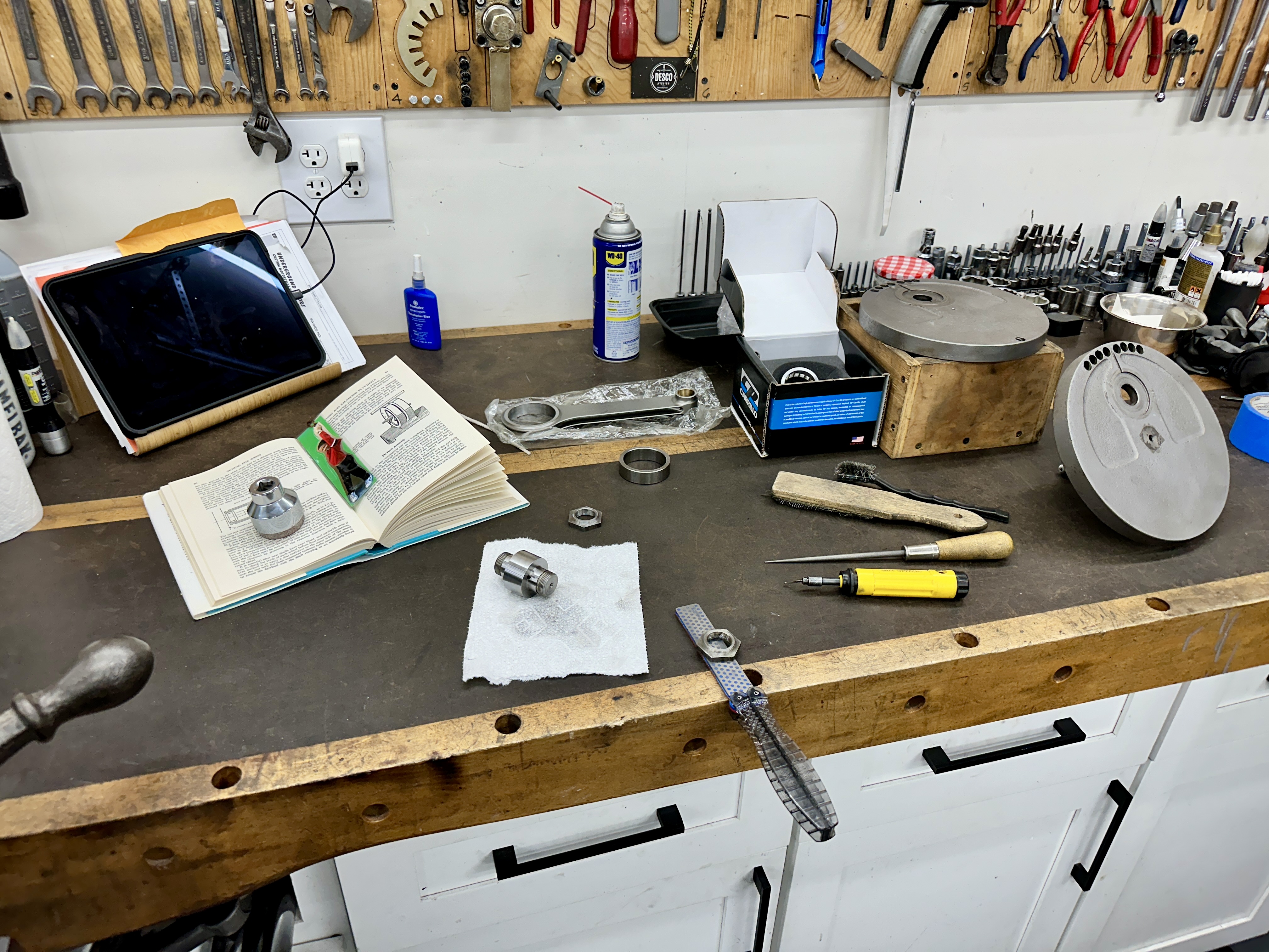
The first step was to carefully inspect all of the related parts and make sure that they fit properly. In the following photos, I am deburring the crank pin nuts using a diamond file and a deburring tool.

Next was to carefully mark the crank pin and the flywheels to make sure that I aligned the critical oiling passages when assembling.


Here is a photo of the rod and related parts:

Next was to install the crank pin into the drive side flywheel using the 12 ton press. Note that I checked that the crank shafts where perpendicular to the flywheels on the lathe using dial indicators prior to this assembly step.


Next was to oil and assemble the rollers and the cage.


Just to be sure that the pin was driven home completely, I switched to the the 20 ton press for the final assembly of the two flywheels. Being careful to align the two flywheels resulted in a near perfect result using a machinist square to check the to alignment of the outside edges. Since the flywheels can only pivot on the axis of the pin, it is fairly easy to check this alignment.


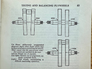
Once these were pressed together, but before installing the nuts, I checked to make sure that the two flywheels were parallel to one another. All of these procedures are very well described my Phil Irving in his book, Tuning for Speed.


CRANK BALANCING
The next step was to balance the crank to the Veloce specified 70% balance factor recommended for an iron MSS. This is actually a relatively simple process, but requires a sensitive balance stand.
STEP ONE:
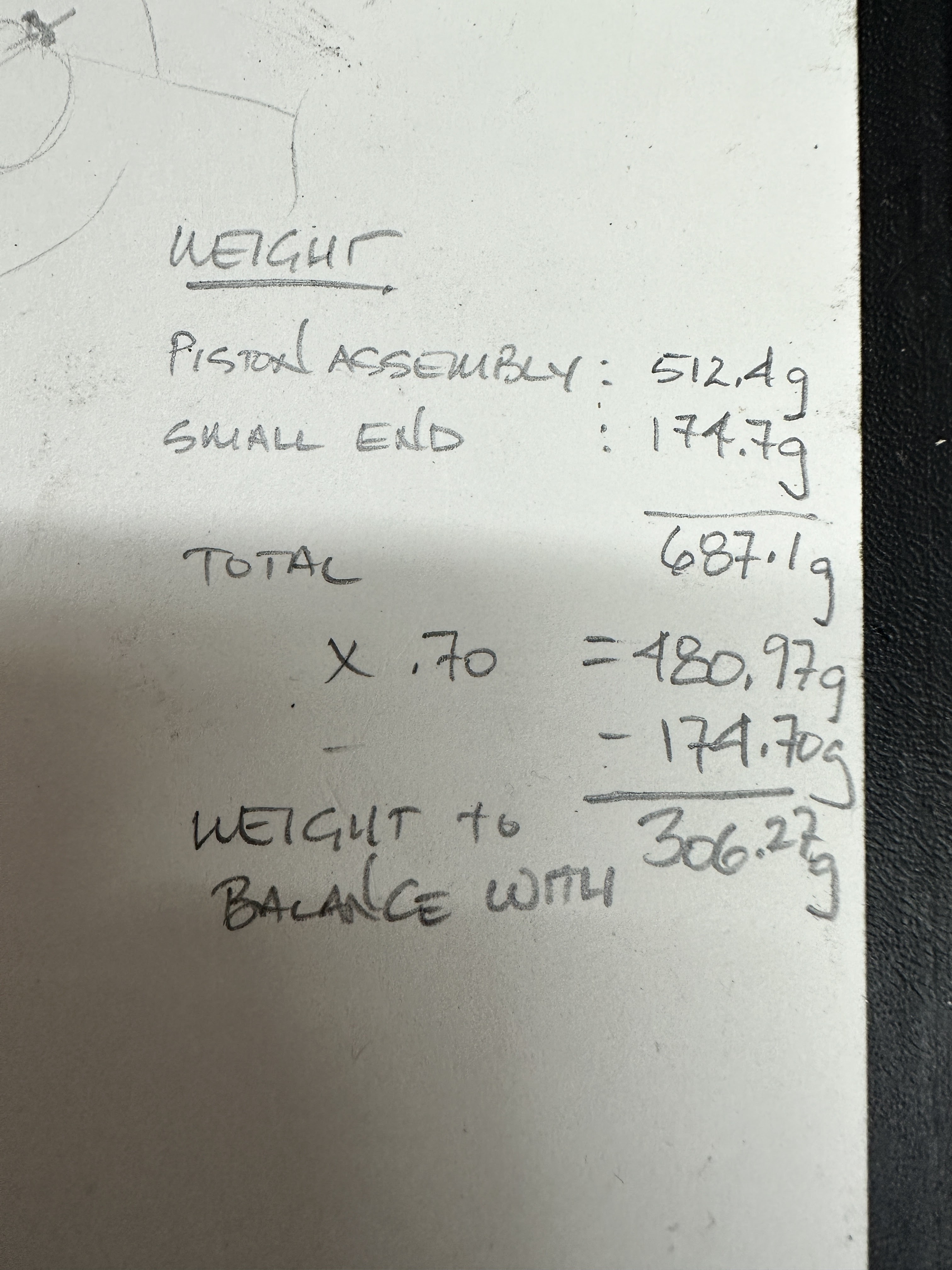
Weigh the piston and wrist pin.

STEP TWO:
Weigh the small end of the connecting rod, making sure that it is horizontal when doing so.


Weigh the container that will be used to add weigh when balancing the assembly. I used a socket with electrical tape blocking the bottom since I will be using lead shot in this exercise.


STEP FOUR:
Measure and do the math.
STEP FIVE:
I machined two bushings with equal outside diameters to enable me to use the balancer since the timing side and drive side shafts are not the same diameter.


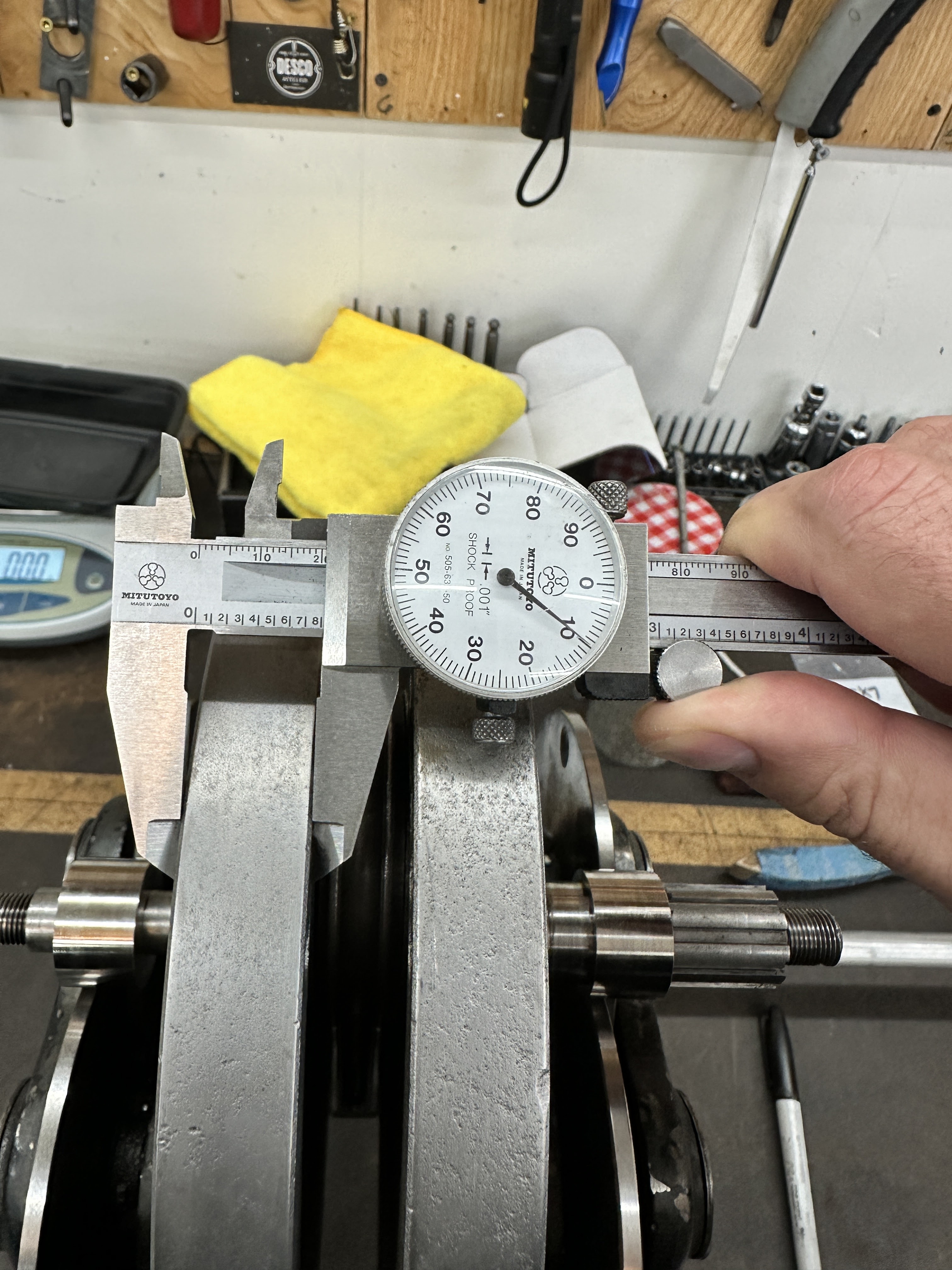
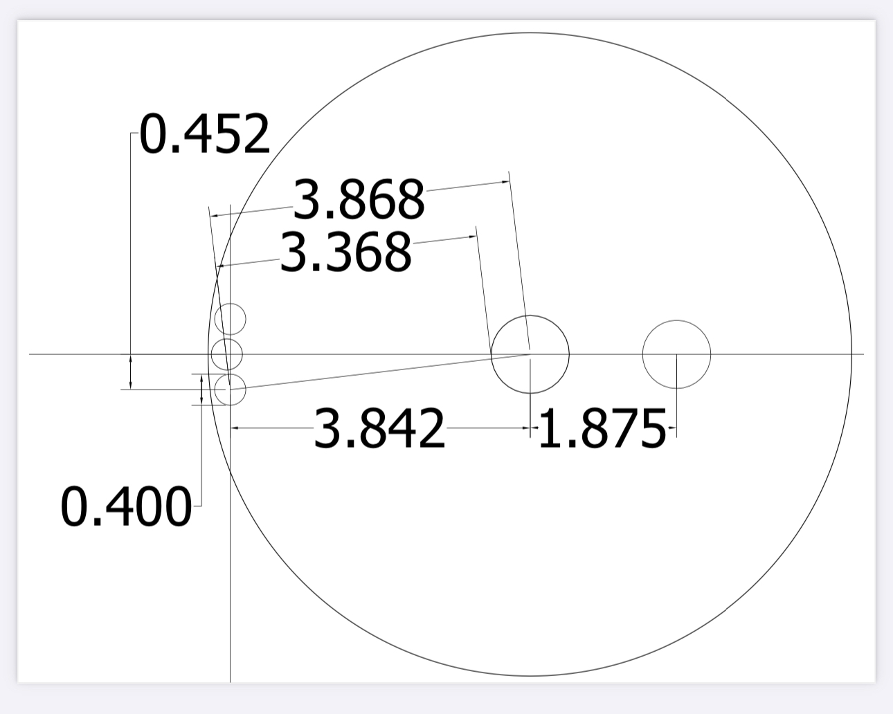
Now that I had figured out the amount of weight needed to get to my desired balance factor, I had to estimate where to remove it from the flywheels. Phil Irving provided some estimates for the eight removed by drilling holes in the flywheel.
STEP SEVEN:
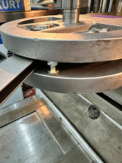
I took some measurements and came up with some theoretical new holes drilled and their locations. This just gave me an idea of where to start, but I approached this slowly and put the assembly back on the balancer to confirm the progress made before drilling the final holes. As it turns out, I did not have to remove as much as I had anticipated to get to my final balance factor. Note that I used bolts with nuts to support the two flywheels while drilling. I did not want to lose the flywheel alignment.


Now that my crank assemble was trued and balanced, it came time to focus on the cases and assembling them.
CLEANING UP THE ENGINE CASES
With the cases split, now was the time to thoroughly inspect each side and remedy any burrs, stripped threads and the like. In comparison with the many other vintage motorcycles that I have worked on, the Velocette castings are some of the lowest quality that I have seen.


April 17, 2025....work continues and will be added here periodically.
Thanks for reading,
Blaise


Comments
Post a Comment